This post is mostly to write down everything in one place for me to review it.
Tracer 900 (2015), lost compression, went to dealership for assessing, came back.
Swapped engine. Old loom and coils used.
Reconnected everything and refilled fluids etc. Recharged battery.
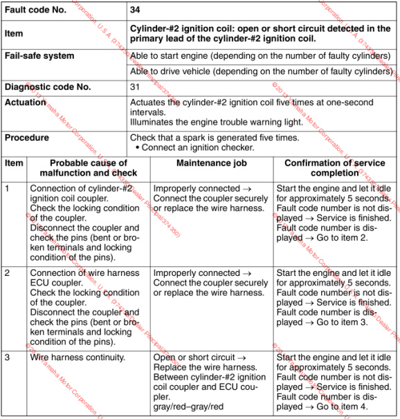
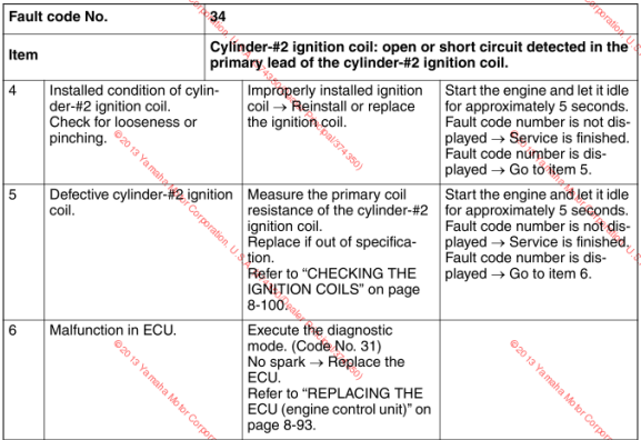
On starting up, ECU reports error codes 33 and 34. Yamaha & Haynes manuals both show this is “Ignition coil: open or short circuit detected in the primary lead of the ignition coil for cylinders 1 and 2”. No other errors including coil for number 3 (would be error code 35).
Fault finding:
Coils have a primary and secondary lead. One lead is the same colour on all three (red/black) and proven continuity from coils 1-2, 2-3 and 1-3. Other lead is a different colour for each. Proven continuity from each of these back to the ECU connector. Continuity fails from red/black wire on all three coils back to the ECU connector, this includes coil 3.
Swapped coil 1 and 3, same errors on ECU.
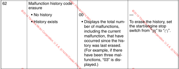
Followed manual’s instructions to clear any errors, errors do not clear. Unsure if this means it is unable to clear error or it won’t clear errors that still exist.
Do not want to refer to dealership as they seem to have fucked me in another issue.
I’d first try a different OBD app to see if that can clear the errors; there may be a more Yamaha (or more MT-09) focussed one for a few quid (“TuneECU” can do extra stuff on Triumphs, for example); that might make “Execute the diagnostic mode” a bit more obvious.
Sincee there’s no change when you swap the coils about I’d expect the problem to be in the wiring or connectors. I’d connect up the meter for continuity and then give everything along the line a wiggle/poke to see if you can break continuity there, also look for any obvious damage.
Thankfully the bike diagnostics have an option to “test the coils” one at a time. Can hear the working coil spark ok, this confirms it’s not an old code and there is still a problem. Swapped coils and cable to confirm all coils themselves are ok.
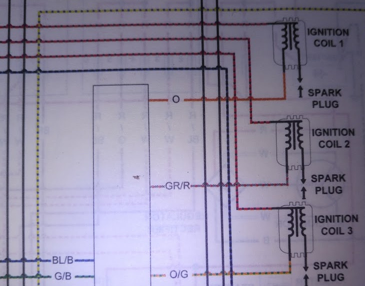
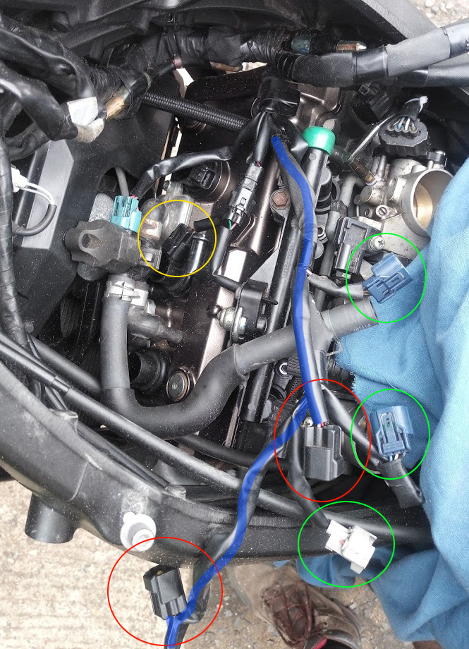
So this is the loom as it stands:
red circle: coil connectors that don’t work.
yellow circle: coil connector that does work.
Blue line: part of loom that these 2 non-working connectors are sat on.
Green circles: fuel injector & 2 TPS that are testing ok.
So I’m guessing it’s a problem along this line as BRS suggested but that doesn’t explain how connectors 1 and 2 are testing connected to 3 ok!
It’s quite strange to have two coils on one branch and the third on another; are you sure you’ve properly identified those? That said, it’s also strange to re-use connectors like that and it’s the odd one out that works…
It’s a bit strange, though. Have you cross-checked cable colours with a wiring diagram to make sure everything’s in the right places?
Yup, all the colours match up. The connectors are different shapes for different tasks like the back of a computer so it’s not possible to connect a coil lead to an injector. The third lead does meet the other two later in the loom, it just comes off a different branch as it’s shorter.
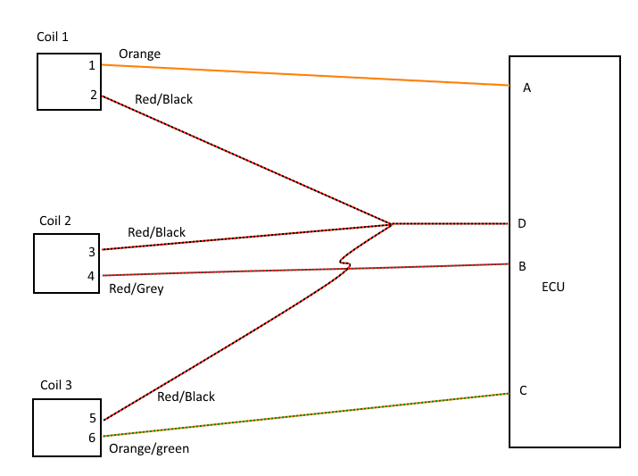
Drew this out another way to try and make sense of my testing.
Red/black wires are common, on the official schematic they link but I don’t know if they’re the primary or secondary coil.
Continuity tests:
1-A ok
4-B ok
6-C ok
2-D fail
3-D fail
5-D fail
2-3 ok
2-5 ok
5-3 ok
What do you mean by primary and secondary coils there? This wiring’s all for the low-tension coils, the high-tension one only contacts the spark plug and the engine casing.
That looks to me like there’s an open circuit between the 2/3/5 join and the pin on the ECU - all the ground lines from the coils show continuity with each other but none to ground itself (have you tested to ground itself, rather than just the ground pin on the presumably-quite-fiddly ECU connector?). That doesn’t support one coil working while the others don’t, though I can imagine a separate fault could facilitate that…
Is there a voltage between D on the ECU and either terminal of the battery, when the bike’s on? And between the wire side and either terminal of the battery for each coil being plugged in on its own?
Turns out part of the problems I need to learn how to read a FUCKING schematic. 2, 3 & 5 don’t go to the ECU, they go to the ignition relay under the seat and they all test fine so the photo with the loom coloured in is all fine and can be ignored.
I’ll now go check what else I’ve missed as it seems that red/black wire is also shared with the starter switch.
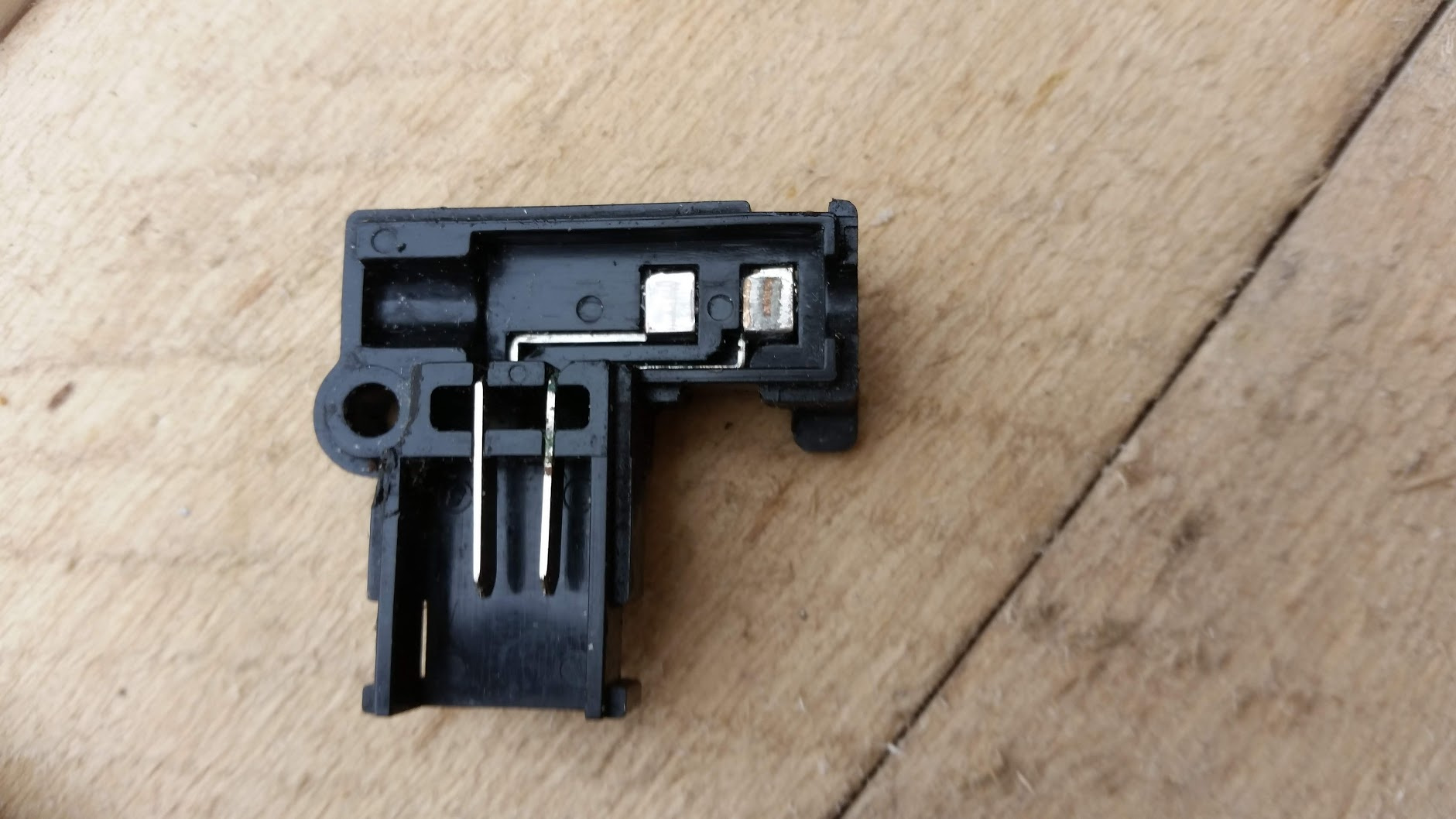
Today I ran through all the diagnostic tests again and something piqued my curiosity. While testing the gear position sensor/clutch/sidestand (ie; the bit that stops the engine running away) I noticed that the clutch lever only triggered briefly during its state change and didn’t stay “off”. Took the switch off and stripped it down to find it had corroded a bit.
Both of the lines from this switch go into the same starter relay so I figure it’s a smart thing to replace it. Look it up on AJ Sutton to find it’s £46 just for this little microswitch! Fuck that I think, pop the part number into ebay and find it’s exactly the same part as used on my fazer 600. Go to my drawers of that bike and that switch has corroded too would have been nice to get a straight replacement but nevermind. Bought a brand new replacement for £11 anyways.
Ran the same test but jumpered the connector, test passed as it should have done but the coils are still failing as before so I’m no further forward really.
From Avi’s tests I’ll check out the ground continuity tomorrow (It’s on the starter and I checked it today). Can’t get a test lead on the connector when the bike’s on, it’s sealed and has to be plugged into the ECU to start up.
Cranking over and not-firing is a very common problem, and with a new block and your having touched every mechanical and electrical connection in and out it’s unlikely to just be the same problem again.
You’re at square one again, but it’s best to view this as of a different game.