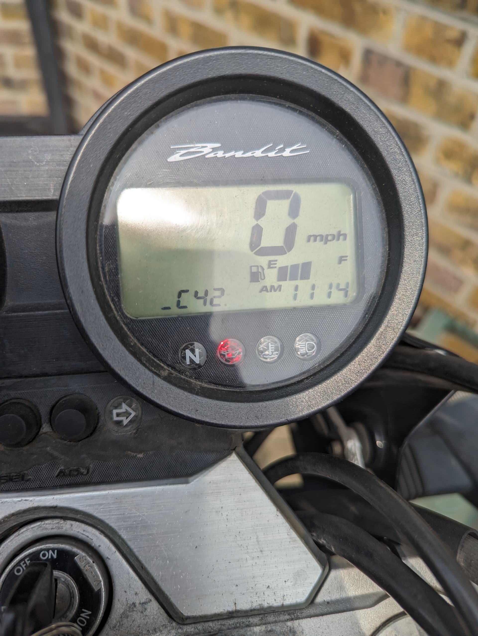
My engine is suddenly refusing to start up. The speedo is showing the C12 fault code, which is the crankshaft position sensor - specifically “The signal does not reach ECM for 3 sec. or more, after
receiving the starter signal.” according to the service manual. Also, in the manual they suggest to do some basic checks like continuity and resistance on the CKP sensor. I’m not electrically able, so would love some guidance. I’m trying to read the diagram in the service manual, but something doesn’t seem to add up. See below:
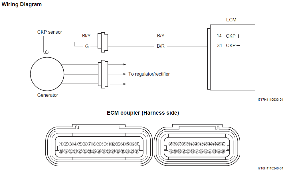
What I gather from the diagram is that the terminals of the plug leading to the CKP sensor are BI + G. So, that’s where I would think I’d need to put the multimeter leads. Yet in the instructions just below the diagram it says to check the resistance/continuity between B + G terminals. But B terminal is supposed to be the one that goes to the ECM. Am I misunderstanding something or are the instructions wrong?
Follow up question, for continuity they ask to use something as ground. What would I use on the bike for that? Is the frame of the bike good enough?
If I was a gambling man I’d wager the signal is not reaching the ECM and that the CKP sensor is faulty but the tests need to be carried out to prove that to be the case.
Yes, both wires go to/from the ECM. That’s how the CKP sensor works, it receives a voltage from the ECM and returns a pulsed signal voltage back which allows the ECM to calculate the crankshaft position for the ignition timing.
The tests in the manual assume either:
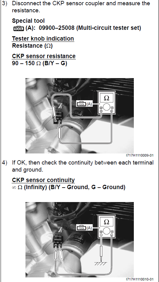
The CKP sensor is faulty. Measuring the resistance between the Bl/Y wire and G wire on the CKP sensor side of the connector (to/from the CKP sensor) expect 90-150Ω which proves the sensor is OK. If resistance is outside that range the CKP sensor is faulty and needs to be replaced.
The wiring is faulty and there is a short to ground. Test for continuity between the B/Y and B/R on the wiring harness side (ECM side) of the CKP sensor connector to ground expect no continuity which proves there is no short to ground and the wiring is good. If there is continuity to ground then the wiring to/from the ECM will have to be checked.
When workshop manuals mention ground they mean ‘chassis ground’ or ‘engine ground’ so any metal part of the frame or engine will do. The grounding path is engine/frame-earth strap-battery negative terminal, if you’re not sure that you’ve chosen a good grounding point, which can be the case when you’re expecting no continuity, it can be good practice to double check by using the battery negative terminal as the ground point.
Note when the ECM detects a minor fault it will either ignore it and the engine runs rough or it goes into simulated (limp home) mode. If the ECM detects a critical fault, such as a faulty CKP sensor, it will go into fail safe mode and shut down all systems until the fault is rectified.
Checked all four terminals (ckp and ecm side plug) one by one connecting it to the frame and battery -. No continuity as expected. Readings remain as ‘1’ throughout without any fluctuations.
Checked for continuity between the CKP ecm-facing plug terminals and the ECM connector (used a needle in ecm plug as openings too small for meter probe). Both terminals show good stable continuity.
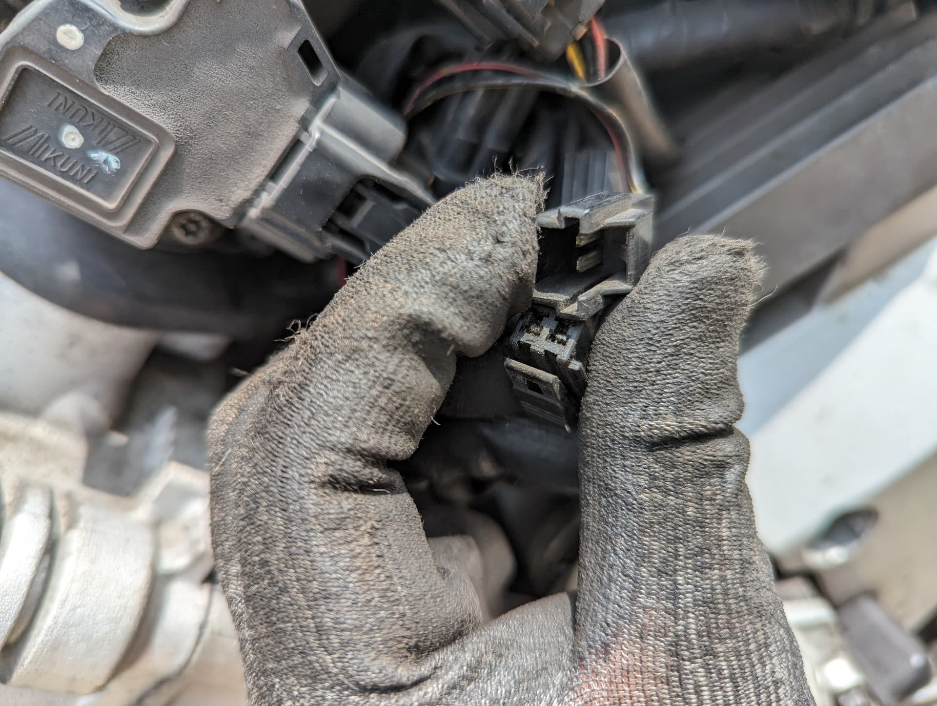
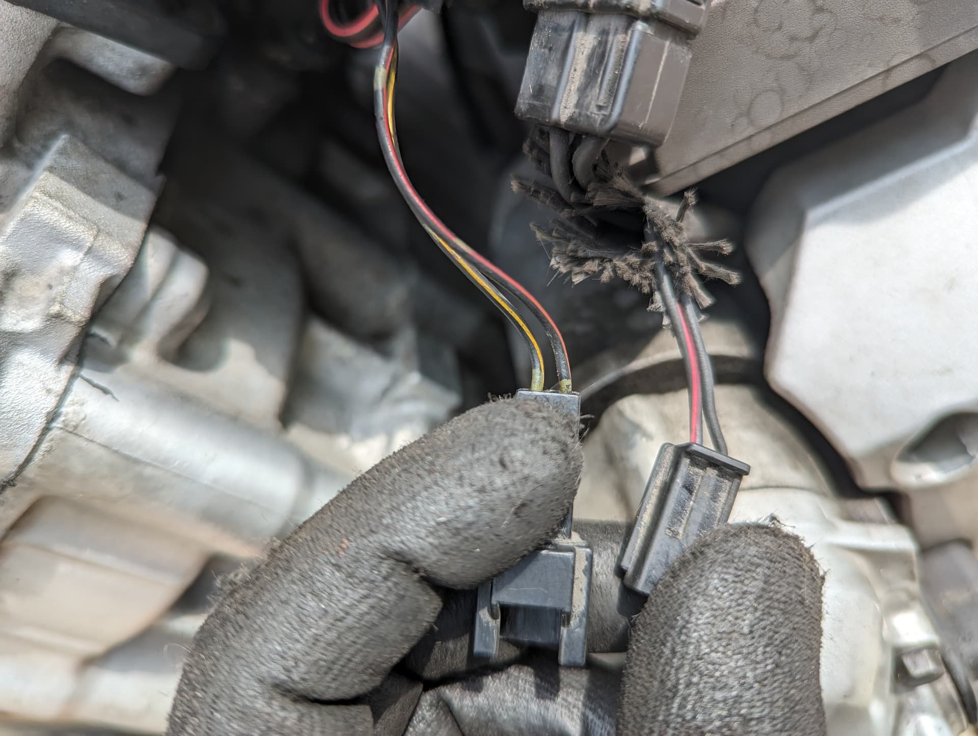
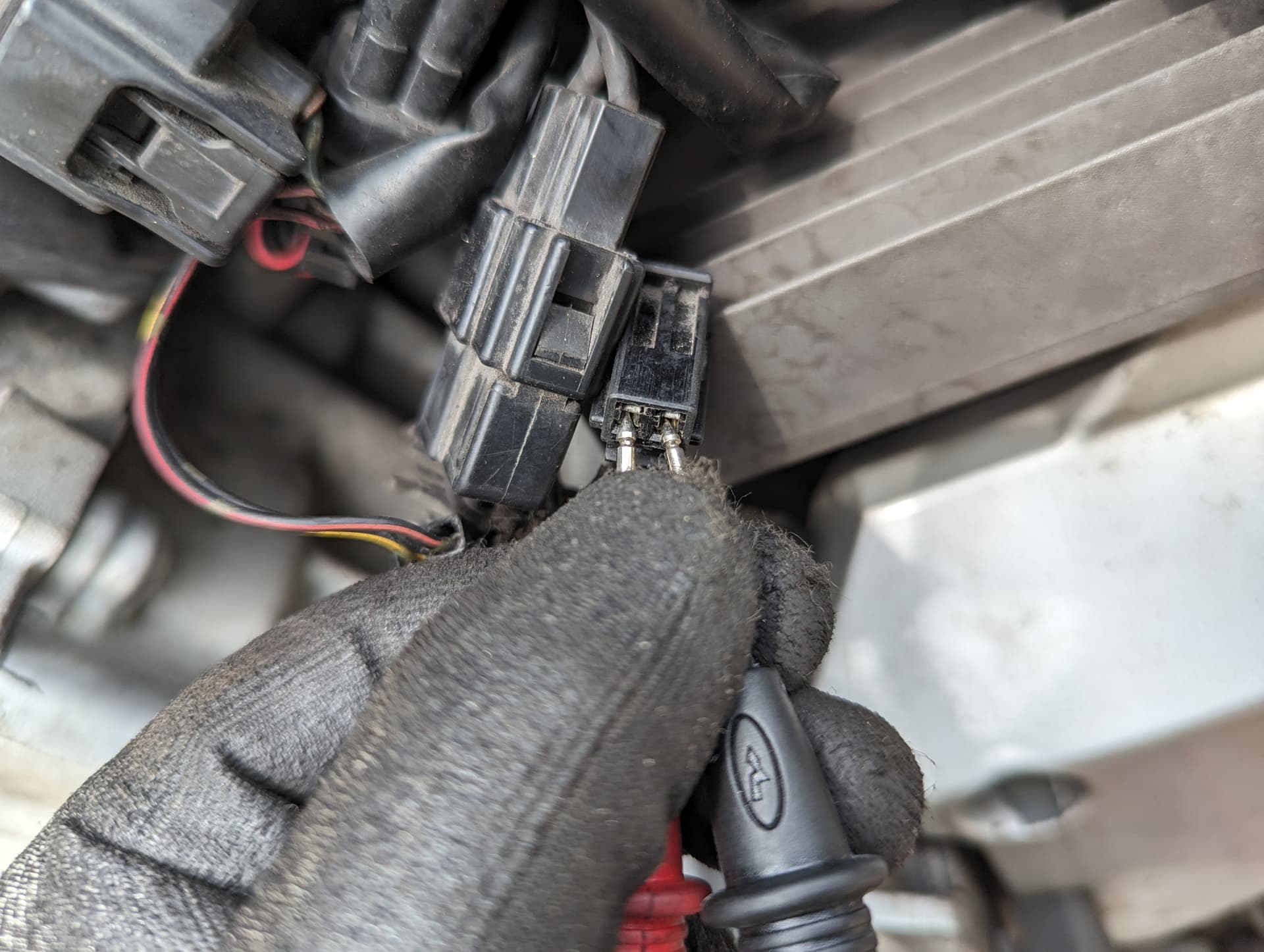
I just realized the Bl, Y, B, G designate the colour of the wires That would mean Bl - Blue, Y - Yellow, B - Black, G - Green. Correct? In that case, my CKP sensor side plug wires don’t match up - they’re black/red and black, not blue/yellow and green as seen in the wiring diagram.
(the ecm facing plug does match the colours, though)
Given my last point, does the polarity matter in this case? Will it cause any issues if I get the polarity wrong when measuring the voltage?
Finally, when I first turned the ignition on this morning before doing these tests, a new fault code appeared - 42. This disappeared after I turned the ignition on/off a few times. The manual says:
“Detected Failure Condition: Ignition switch signal is not input to the ECM.
Check for: Ignition switch, lead wire/coupler, etc.”
Yes, B/Y=black/yellow, B/R=black/red, Bl/Y=blue/yellow and G=green.
Assuming the sensor was working I wouldn’t worry about the wire colours, it could be that the sensor was changed previously for a generic pattern part with different wiring colours.
If you connect the multimeter probes the wrong way round you’ll just get a minus reading of say -2v instead of 2v or if you want to hook it up correct check which wires pair off through the connector, I think you’ll find it’s Bl/R = positive and B = negative.
This could be many things, dirty or corroded switch/connector contacts or a faulty switch and may not be confined to the ignition switch it could also be the: kill switch; side stand switch; neutral switch or any or their associated connectors/wiring.
Ok. So, just to confirm that I’m doing everything right.
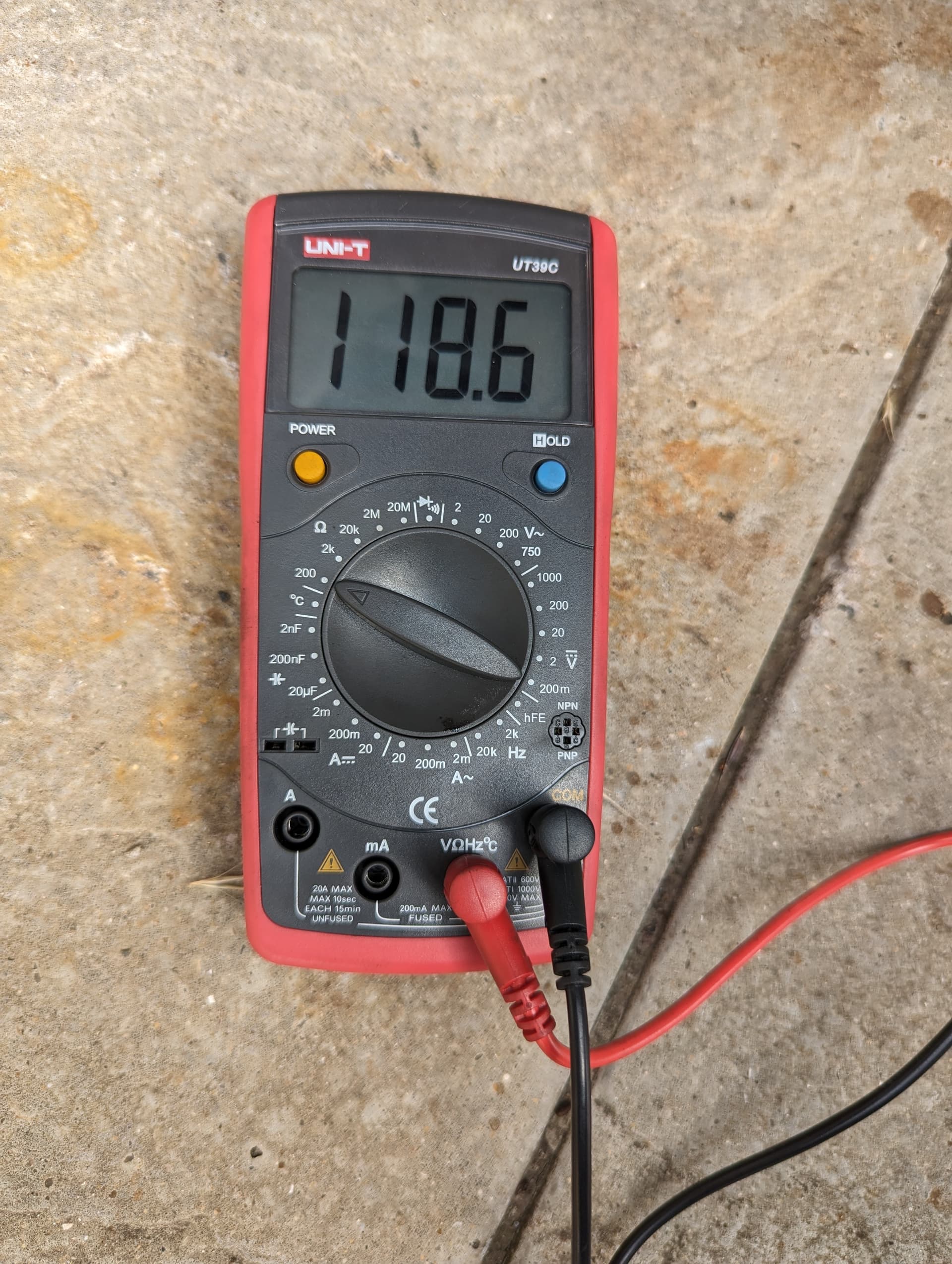
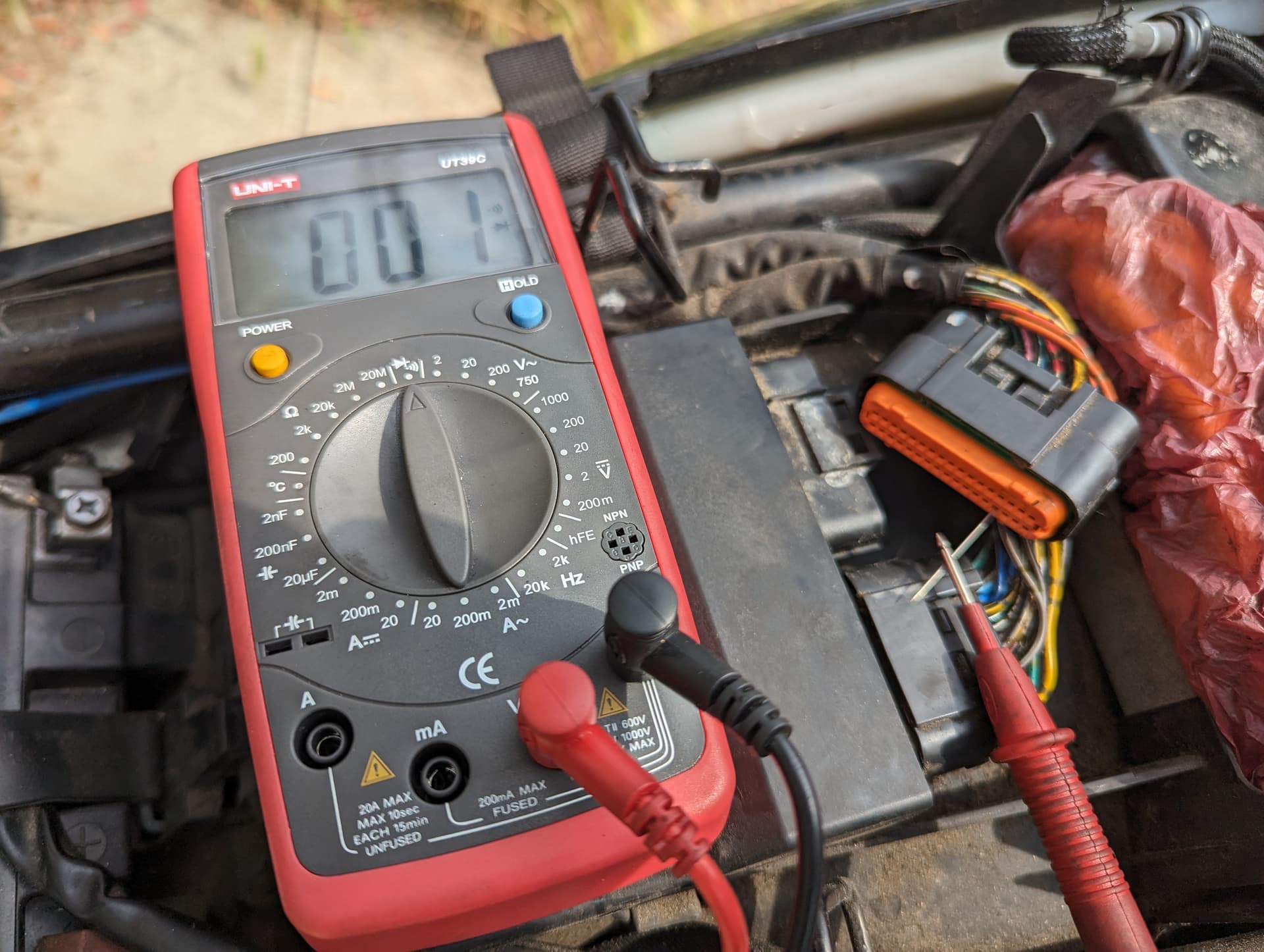
I’ve put the multimeter on the 20 DC Voltage setting. Measured the battery to confirm the multimeter works (showed about 12.55V; it was 12.8V this morning but I guess all the testing drained it a bit).
Held the engine starter button (cranking the engine) for several seconds while watching the multimeter readings.
Doing this shows me a constant 0V while I try to start the engine. There is no reaction at all on the multimeter.
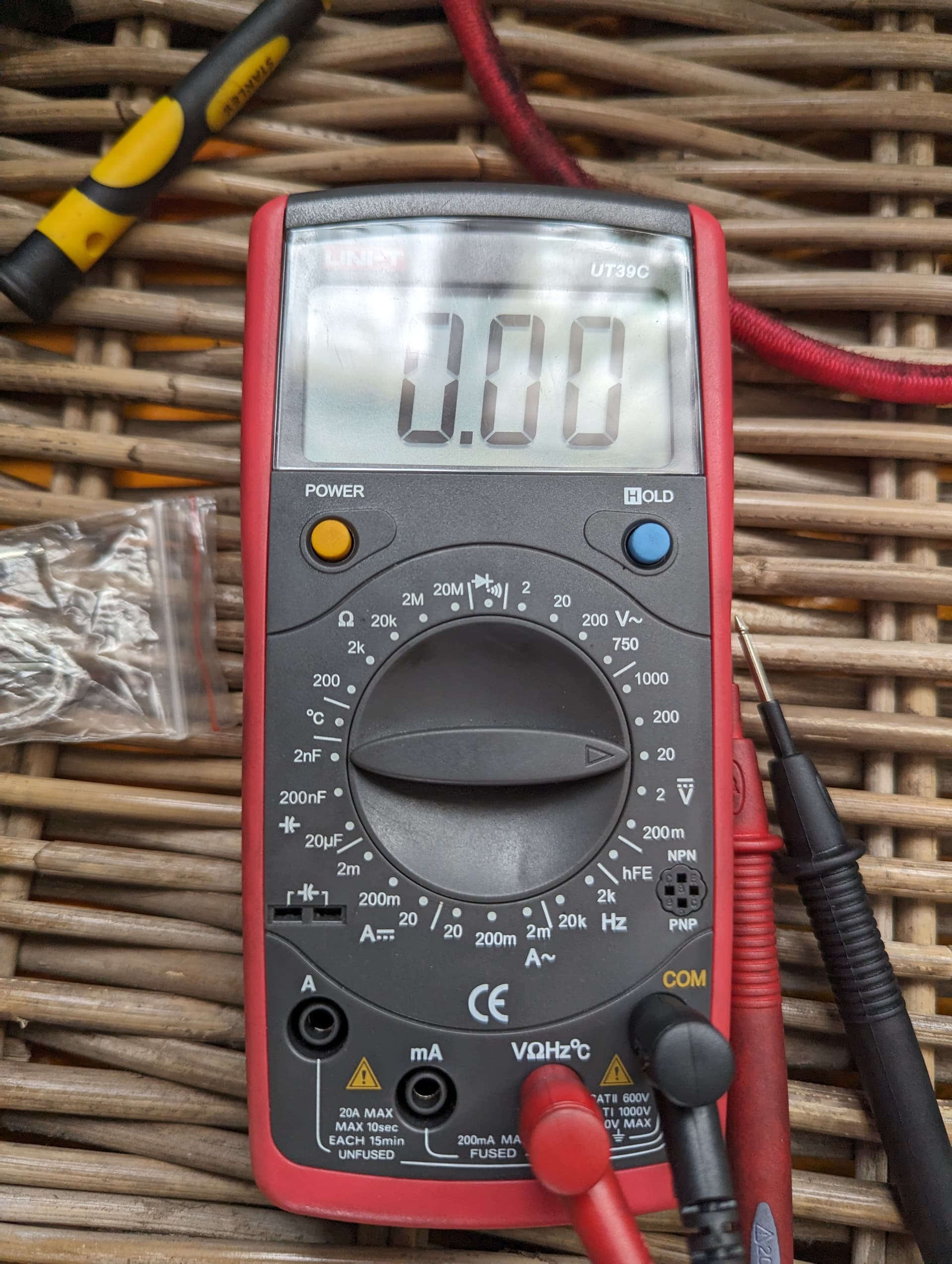
Just to be sure I was making contact with the terminals, (after I stopped cranking the engine) without moving the probes I switched the multimeter to measure resistance again, and it again measured around 120 ohms. Then, I moved the probes to the back of the plug and measured the resistance for the terminals there - same 120 ohms; switched to 20V DC, pushed the starter - 0V again. Also, tried switching to 2V DC setting - no changes.
By the way, this is the sound that the bike makes when I’m holding the starter button (begins at 2sec).
Sorry, I’ve never been that clear about the automotive definitions and sounds.
That electrical whizzing sound in the video is the only thing I can hear when I push the starter button. I assumed that was the cranking?
Sorry, just watched your last two videos. When you first turn on the ignition that sound is the fuel pump priming, when you press the starter button the fuel pump primes again, this is probably because the ECM re-sets due to low voltage issue in the starter motor circuit. I think I hear the starter relay click when you hit the starter button but the stater motor doesn’t crank the engine which would also indicate a low voltage issue in the starter motor circuit.
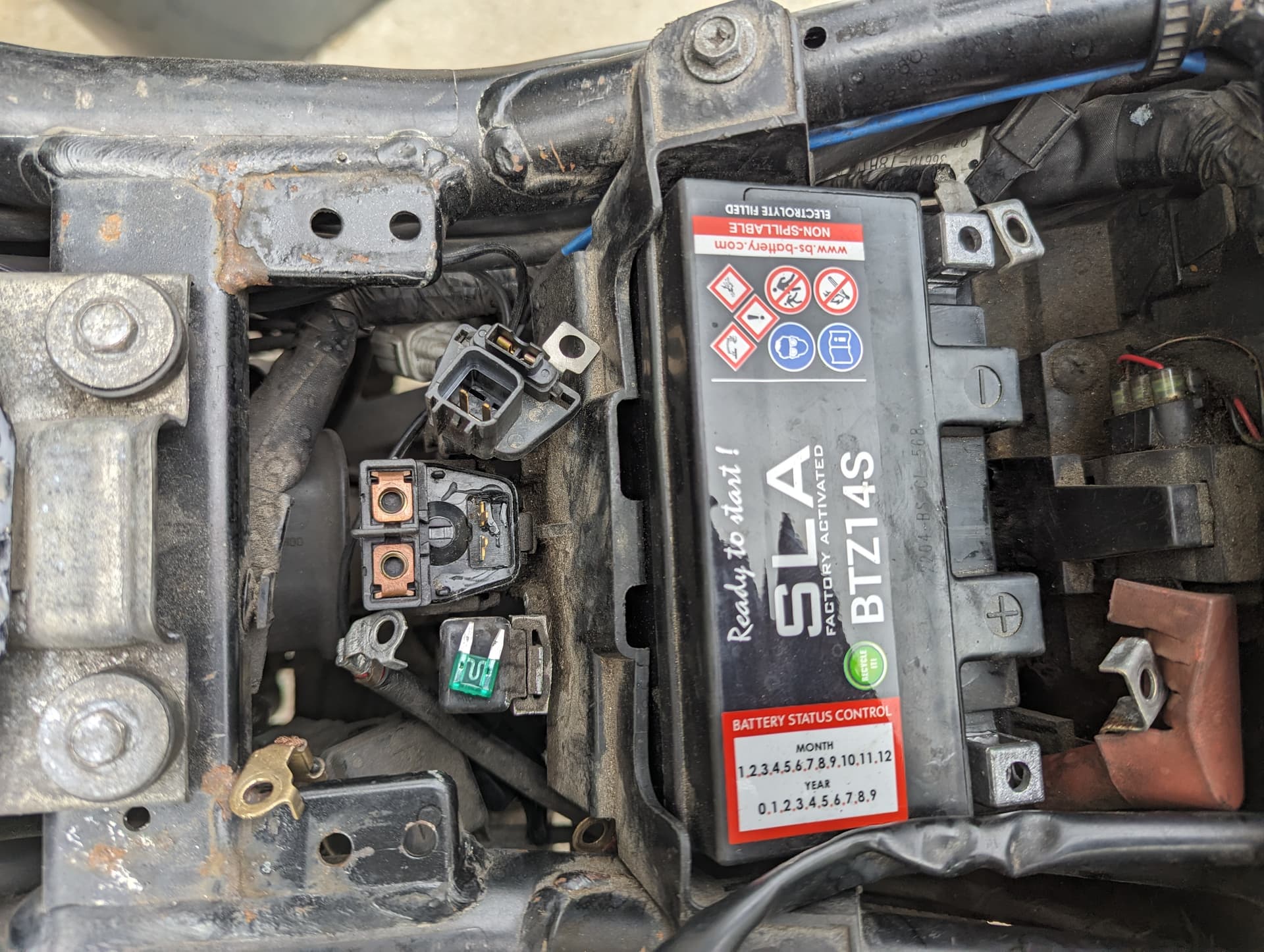
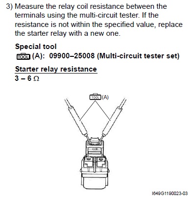
Check the battery terminal connections are tight, check the starter relay connections are tight, check the starter motor connection is tight. Test the starter relay. Test the starter motor.
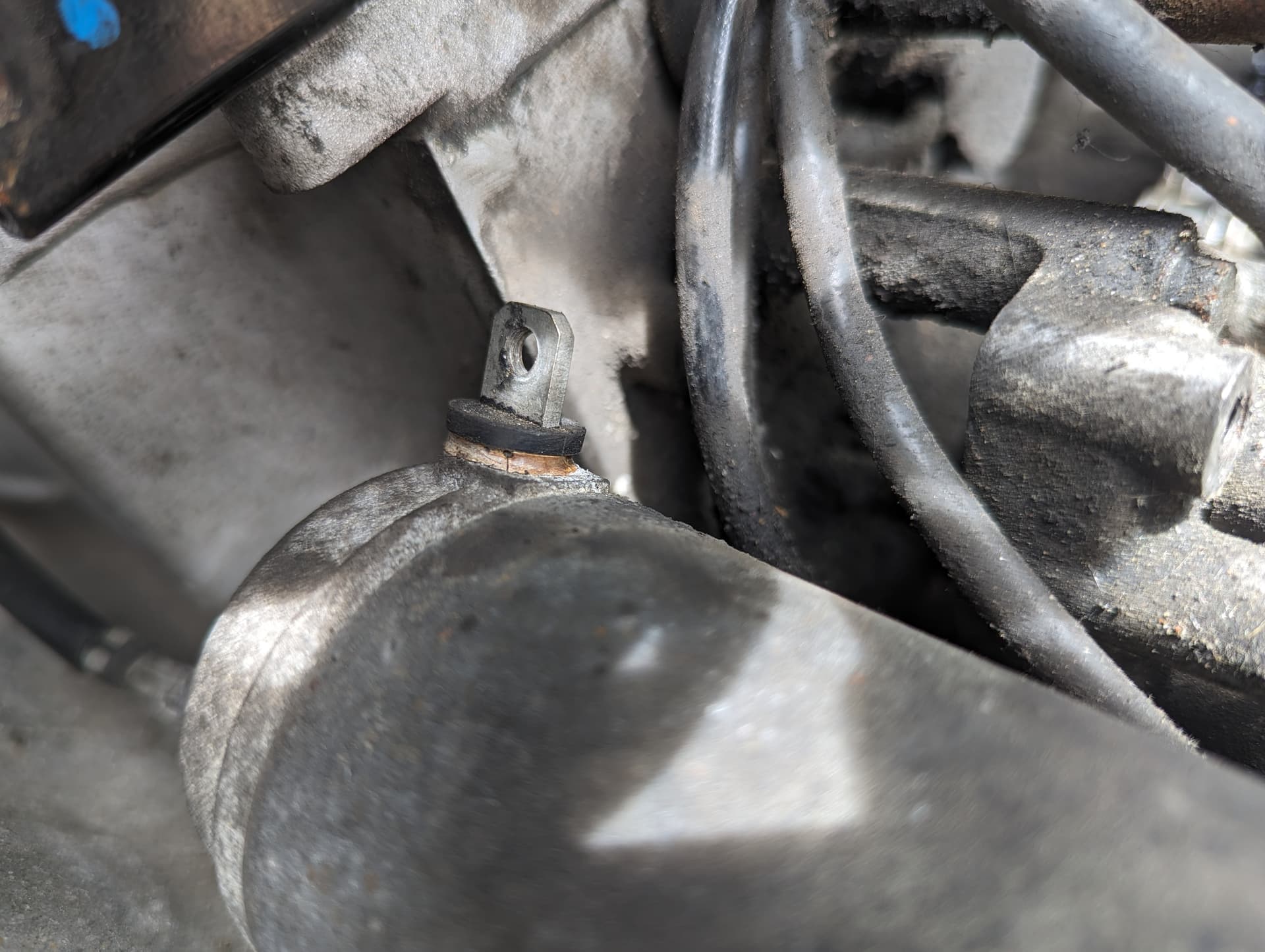
Cleaned with wire brush and contact cleaner all the battery, starter relay and starter motor connections and retightened. Most seemed fine. The motor terminal to the relay looked slightly burned.
Wanted check for the click of the starter relay and continuity as per manual, but all I have is big jumper cables that won’t fit the terminals, so didn’t test.
Assembled everything back together. Bike started up straight away. Annoyingly, forgot to try starting the bike before I did all this work, so now I’m not sure if it was something that I did that fixed it (although everything appeared clean and tight) or the bike just needed a holiday as well.
Since I’m unsure how long this will last, I’d like to finish the tests, so I’m ready in case it doesn’t. Hence, a couple of questions:
Which jump leads can I get to connect the battery to the starter relay directly to test it? It has to be small enough to fit inside the starter relay but thick enough to handle the amperage/voltage of the battery. I tried looking up some on amazon, but there is so many different types and gauges and lengths with different connectors and prices from a few pounds to hundreds… my head is spinning.
In order to test the starter motor the manual says: “Check if the starter motor runs when its terminal is connected to the battery (+) terminal.”. Do I first need to disconnect the battery or/and the starter motor from the starter relay or can I test it while everything is connected and in situ?
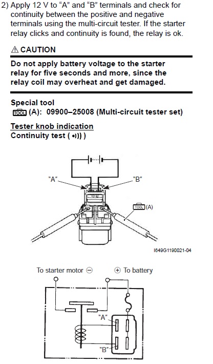
No need to worry about amperage the test is carried out with the relay disconnected and only requires a 12v connection across terminals A & B to energise the relay coil to check for the click and continuity across the positive and negative terminals. I use mini crocodile clips similar to these Alligator Clips Mini Crocodile Clip 12v Wires Cable Small Leads Electrical Croc | eBay
Test it while everything is connect but not with the mini crocodile clips, here there will be high amperage, for that test I’d use something sililar to these Equip 1.5 metre 80 Amp 5mm2 Motorcycle Jump Leads/Booster Cables 5010373080955 | eBay
connect the jumper lead to the shank of a cross point screwdriver and use that to make the connection to the positive terminal of the relay by engaging it on the cross point screw head.
If the fault returns that means you’re dealing with an intermittent fault which you’ll only 100% resolve if testing while the fault is present.
Hi… You shouldn’t be checking for DC. A two wire CKP which is an inductive type produces AC voltage… This is a problem in most old manual. It is stated the to put the knob at DC voltage. A hall-effect type or 3 wire sensor will produce DC voltage up to 3.5 and above…
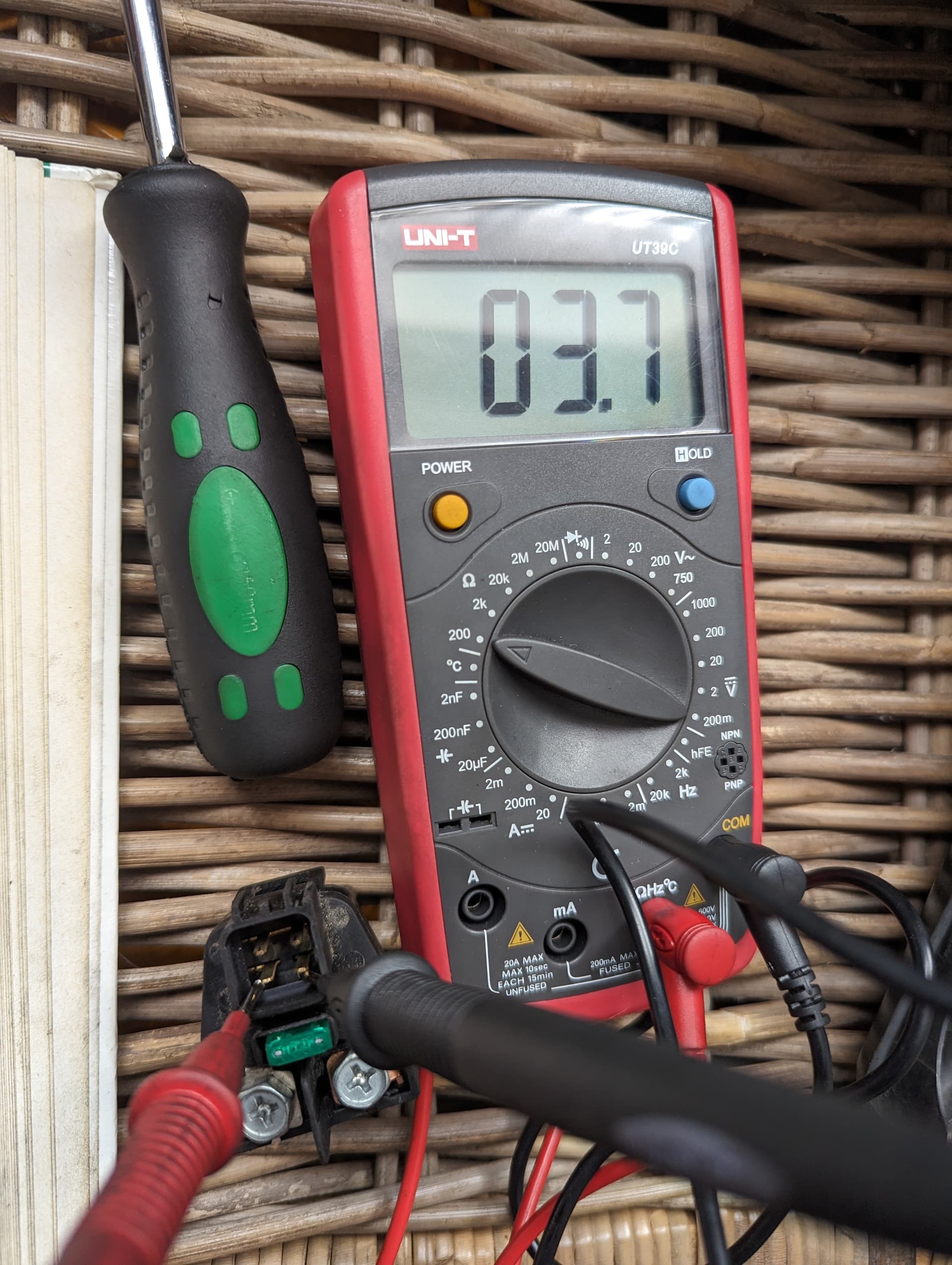
Welcome to the forum. You’re a bit late to the party as the thread is from a year ago. Not sure what CKP is, but the 3.7 I mentioned in my previous post was for Ohms not Voltage.
The CKP is the CranKshaft Position sensor, it produces an AC output signal that the ECM uses to determine the exact positions of the crankshaft and camshaft throughout it’s 360˚ rotation. That said the manual states to measure the sensors peak voltage in DC voltage (solid line over dotted line) and specifies it as “2 vDC and more”
Ah, didn’t read through the whole thread. I did mention CKP a few times in the beginning, but it’s been so long, completely forgot. In any case, bike’s been starting up fine since then.