First something probably dumb, just to confirm that connecting the positive terminals of the battery and a switch source will have no effect on each other?
And the actual question, on a bike would a relay protected by an in-built resistor be fine or would it need a diode?
The background, incidentally, is to use a relay to enable a light switch to power some LEDs from the battery only when the bike is powered. However if the lights are already on when the bike is turned off, the lights should stay on until the switch is opened.
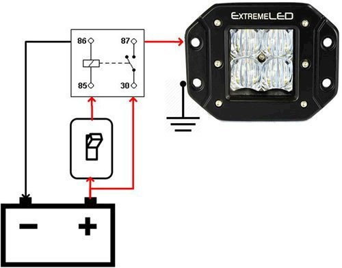
So the battery goes to 30 and 87 to the lights. The switched connection goes to 86, with 85 to ground via a switch. But 87 is also connected to 86, so that once the coil is engaged from the switched source it will be powered by the battery until the circuit is broken.
This is a good diagram to follow, used it for my extra lights on my Defender. If you only want them to work when the ignition is on then just take a live feed from something like the head lights.
The bike has a switched feed specifically for accessories, but it takes a 7.5A fuse and already powers OEM heated grips plus a USB and TomTom. So the lights use the battery to not risk frying the wiring. Plus using a relay means only the tiny current needed to power the coil goes though the handlebar switch.
So that is what I am already doing. Battery connected through the relay with the switched connection powering the coil. Unlike your diagram I have the switch on the ground side of the coil, though I cannot remember why. Something I read made it sound like a better option.
Anyway, the lights are not very good (they were cheap enough to have been worth the gamble) and now one has died. So replacing them is a good time to improve everything else. Including making it so the lights stay on until explicitly turned off. Then I can attach an alarmed disc lock without having to fumble in the dark, or setting it off by having to locking the steering after.
But I never considered needing to protect from collapsing magnetic fields. Who does? As the relay I am using has no in-built protection I can also use it as a chance to replace that with a micro relay to save a bit of space, but the only ones I can find use resistors for protection. Yet everything I read talks about diodes and says resistor are only for certain circumstances, so I just want to be sure it is okay. Mind, the unprotected one does not seem to have done any damage.
I was with you up until “collapsing magnetic fields” 
I know, that is why I need help!
When you suddenly break the circuit that is powering the coil it collapses the magnetic field it created to move the contacts to close the circuit in the relay.
And at that point everything basically gets reversed: instead of the energy from the electricity through the coil becoming a magnetic field, the energy from the magnetic field collapses back into the coil. Which means you get a sudden high voltage spike that needs to be discharged and can do damage.
This is different to the coil in an electric motor. When you cut the power to that it slows down rather than suddenly stopping, so the field collapses more slowly preventing a big spike in the circuit.
Putting a diode between pins 85 and 86 on a relay, i.e. negative to positive direction, means that when the circuit is broken the current gets diverted though the diode and back into the coil. And it goes around and around until it burns itself out.
At least that is how I understood it.
It is the same sort of principle as an induction coil. 12V gets passed through a big coil to create a magnetic field. When the coil is charged the circuit gets broken, the field collapses, and it creates a spike of several thousand volts which are used to create a spark in the plugs.
I probably messed that up, this is why I need the likes of NT to know things. I just want to crimp terminals, not know about electromagnetic fields like someone in Star Trek.
Not sure I understand. The 7.5A fused accessory circuit should be capable of powering heated grips, SatNav and LED lights. To do what you want is not a good idea that said I think a 5 terminal changeover relay with a diode may be what you’re looking for. That should give you ignition on/lights on, ignition off/lights off and allow you to turn the lights on/off when the ignition is off. You’ll need to fit fuses before pin 30 and after pin 87 and a fuse & switch after pin 87a. The downside is you could forget to turn the lights off or some joker could turn the lights on for you and flatten the battery. A better idea might be to have a dedicated LED light powered from a couple of AA batteries, think torch but something a little more built in and factory looking.
Tbh I think you may be overthinking it. The spike caused by switching off a couple of LED lights will be minute, relays should be more than capable of coping with it without any issue. My Defender runs four 6inch LED spots through a single relay with no issues whatsoever.
The grips peak at about 40W (3.3A) and the TomTom is 1.2A (which seems reasonable given it powers a screen and a bluetooth connection), so that only leaves 36W, assuming the USB is not being used (which admittedly it rarely is). Ideally I would like 2x 20W lights as the headlamp on my bike is awful, and it is an LED module so not easy to do anything with.
Leaving the lights on and draining the battery is definitely a risk, but should be an easy one to avoid. But the switch would not be able to turn the lights on unless the bike is also under power.
When the bike is turned on the switched connection will power the coil. But connecting terminals 87 to 86 means that the main circuit through the relay (30–87 to lights to ground) will still power the coil (30–87 to 86–85 to ground) after the bike is turned off. But when you open the switch on the bars to break the circuit, the coil powers down so it no longer has a connection to the battery. So it needs the bike to be powered again as only the switch source can power the coil.
What I am describing (connecting 87 to 86) seems to be a standard way of using a momentary switch to power a relay, but everything I have read it has always been doing this from a single power source. I know that simply connecting the positive terminals of two batteries has no effect, and when making a circuit to ground they just work in parallel to increase the available current.
So I just wanted to be sure that a bike would not add anything that would be affected by essentially connecting the battery positive to the accessory positive which presumably has electronics behind it.
And most of the relays I have seen only include a resistor for protection instead of a diode, at least going by the printed diagrams, so I was wondering if that should be okay.
Here is an example:
And why do you also need a fuse after terminal 87 if the one from the battery is already rated for the wiring?
I probably am, given I am currently using a relay that has no protection, but it is better to do it properly. And the spike would be on the coil’s circuit, so the risk will be to whatever Honda have included on that.
Peak battery voltage can be as high as 14.5v therefore when applying Ohms Law assume the battery voltage to be 15v not 12v. That gives a maximum 108W or 7.2A at 15v for the grips, Satnav and lights. I’d run the lights via a switch off the accessory loom, upgrade the fuse to 10A and note the 12v socket is limited to 40W. I wouldn’t worry about the wiring it should be good for at least 15A if not 20A.
The additional fuse after pin 87 was to future proof the circuit.
I still think your best option here would be an independent switched light source run off a pair of AA battery’s.
Quick related question, how many amps maximum would you consider safe for a circuit from the battery-ish to the bars and back using 0.75 mm² gauge wire.
I have seen so much contradictory information, up to 15A over 10 feet at 12V which seems a lot.
I normally buy cable by its Amp rating. To compare Halfrauds 17A cable has 28 x 0.29 mm diameter strands, by my calculation that is 0.67 mm². So a 15A rating for a 0.75 mm² cable isn’t too far off but note cable rating can vary according to construction, operating temperature, any additional insulation, voltage drop etc.
I assume you are using a multi stranded cable and not a single core wire. Its a mistake I make time and time again in calling cable wire.
Yes, multi stranded. I normally buy automotive cable by the metre from eBay, such as this ad.
https://www.ebay.co.uk/itm/Single-Core-0-75mm-12v-Thinwall-Automotive-Auto-Marine-Cable-Wire-Wiring-Loom/124229027783
I just picked that ad at random, but it gives a maximum load of 14A, but does not give a circuit length which is why I am sceptical of just going by that as an absolute maximum for something much shorter.
Normally 1.5 mm² cable is okay, no space is so small that it makes any difference. But with 0.75 mm² cable you could attach two connectors to one circuit simply by crimping two wires on the pin of one of them (as they are invariably 1.5 mm²). Which allows a neater solution than using a butt connector as a splitter.
Now that I am out of isolation it is time to get the bike back on the road. Which starts with some surface rust and a good clean after four months under cover. Then comes tidying up my electrics.
It is a complete a mess under the seat as it was all done in a bit of a rush last year at my dad’s. That will include replacing the USB socket on the bars, which were already rusted inside despite a waterpoof cover and never being used in the rain, so may as well do the whole job now.
All new relay question!
The switch for the lighting contains an inbuilt LED, it works by taking a single 12V input with separate earths cables for the switch and LED.
I would like the switch to illuminate only when the lighting is lit.
In the absence of suitable DPST relays, it seems the solution is to use the switch to power the coils of two relays in series. One of the relays enables the lights, and the other sits between the LED in the switch and earth.
Simple enough, but along with a relay to provide a switched connection from the battery, I will end up with five and I am not sure I have the space for that.
One thought, would it work if I connect the LED earth to terminal 30 on the lighting relay, so that the circuit goes battery +, to LED, to relay 30, to relay 87, to lighting, to earth? Or not if the relay switch is open.
This would presumably require diodes between the battery and the relay, and the LED and the relay? Would it also need a resistor between the LED and relay so that the lighting has to draw its power directly from the battery and not through the LED?
Or is there a simple alternative? Or is it just nice to have but more complicated than it should be so really not worth the effort?
Ironically my relays are SPDT ones, so it would be very easy to work the opposite way (LED illuminated when lights are off) by just wiring the LED earth to terminal 87a.


