


How do I work out which wiring I need? I have an old lathe which needs rewiring and there’s no markings on the cable, it’s 240v, one cable has two wires running through it, the other 3
Is it a myford lathe and what is the motor
They used different motors over the years
Probably need a bit more info
You will need to know the voltage wattage and amperage or at least 2 of to work out the cable.
Its a case of
Wattage / voltage = amperage
W
---------
V x A
If you need to know wattage and you know the voltage and amperage you multiply them together
Ie kettle is a 3000w kettle
Voltage is 240v
To know amps
3000/240 = 12.5 a ( round up to 13a )
To know voltage
3000/ 12.5 =240
To calculate wattage
240x12.5=3000w
Type in to google myford lathe wiring it gives a lot of info
The brief read i had it COULD be the three core cable is your mains input cable that would have a plug on and the two core COULD be an external stop/start or reverse switch
hi Curtis , I take it its designed to run from 240v like mine so just check the motor data plate to be sure . a 3 phase motor would have a 4 core cable running to it anyway and the plate would state 415v . assuming you have a single phase 240v motor then the phase/live cable would go down a 2 core cable to at least an on/off switch then back to the motor . a 2.5 sq cable is totally adequate , do you have an on/off switch and / or a reverse switch that came with the lathe ? .
a Dewhurst switch is the standard though I have separate rocker switches on mine .
if you already have 2 cables then I assume some switchgear is there as well .
if you have no switch but do not require reverse at the moment then it is just a case of doing a continuity check with a multimeter to ascertain that the live on the 3 core comes on to one core of the 2 core and putting a switch between both cores of the 2 core and checking that onto the motor .
see you on thurs and can go through a wiring schematic for the ml7 if you bring a printout of one along with you …or just some info of your particular motor will do as a start
just checked some wiring schematics and really need to know the exact motor you have as you may have a start and also a run winding so ignore the previous post of just switching the 2 core
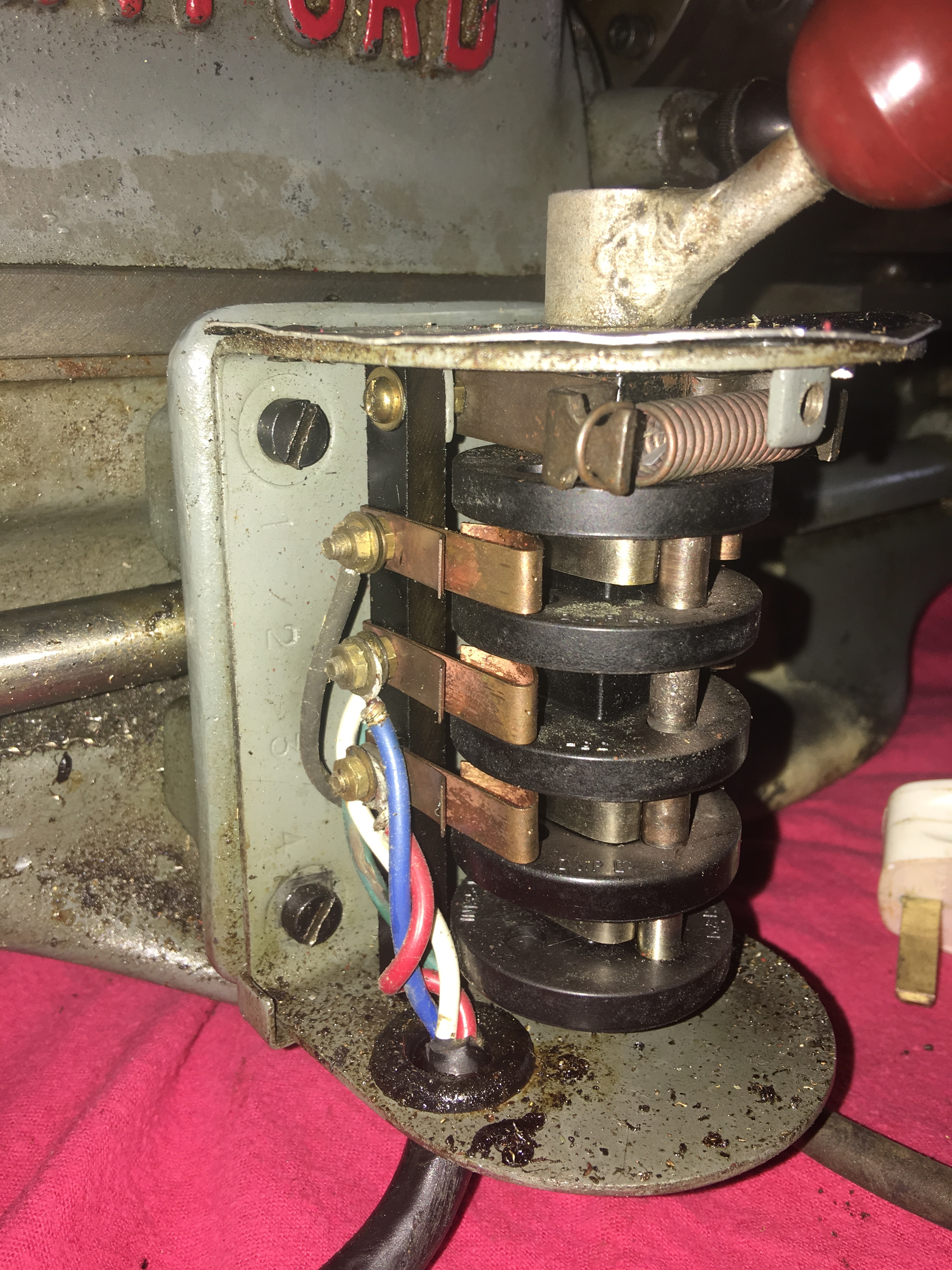
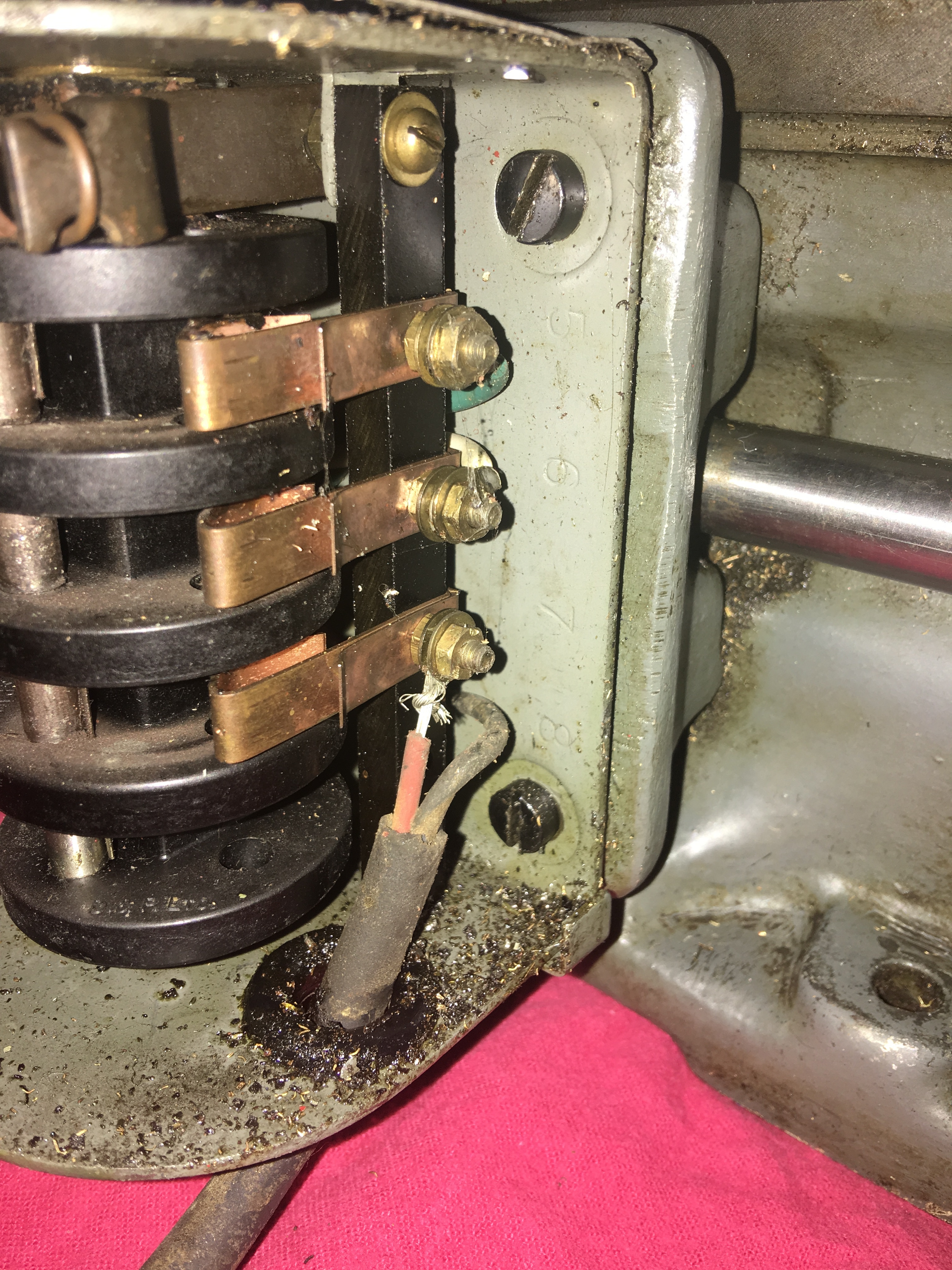
So Just got back down to the Garage. It’s A British Thomson Houston motor, assume it’s single Phase as that’s what it was wired up as. The forward/reverse switch is Dewhurst.
And the Cable running from the forward/reverse switch to the motor has 4 wires not 3! The cable from the plug socket to the reverse switch has two wires
As for motor plate I can’t seem to find it?
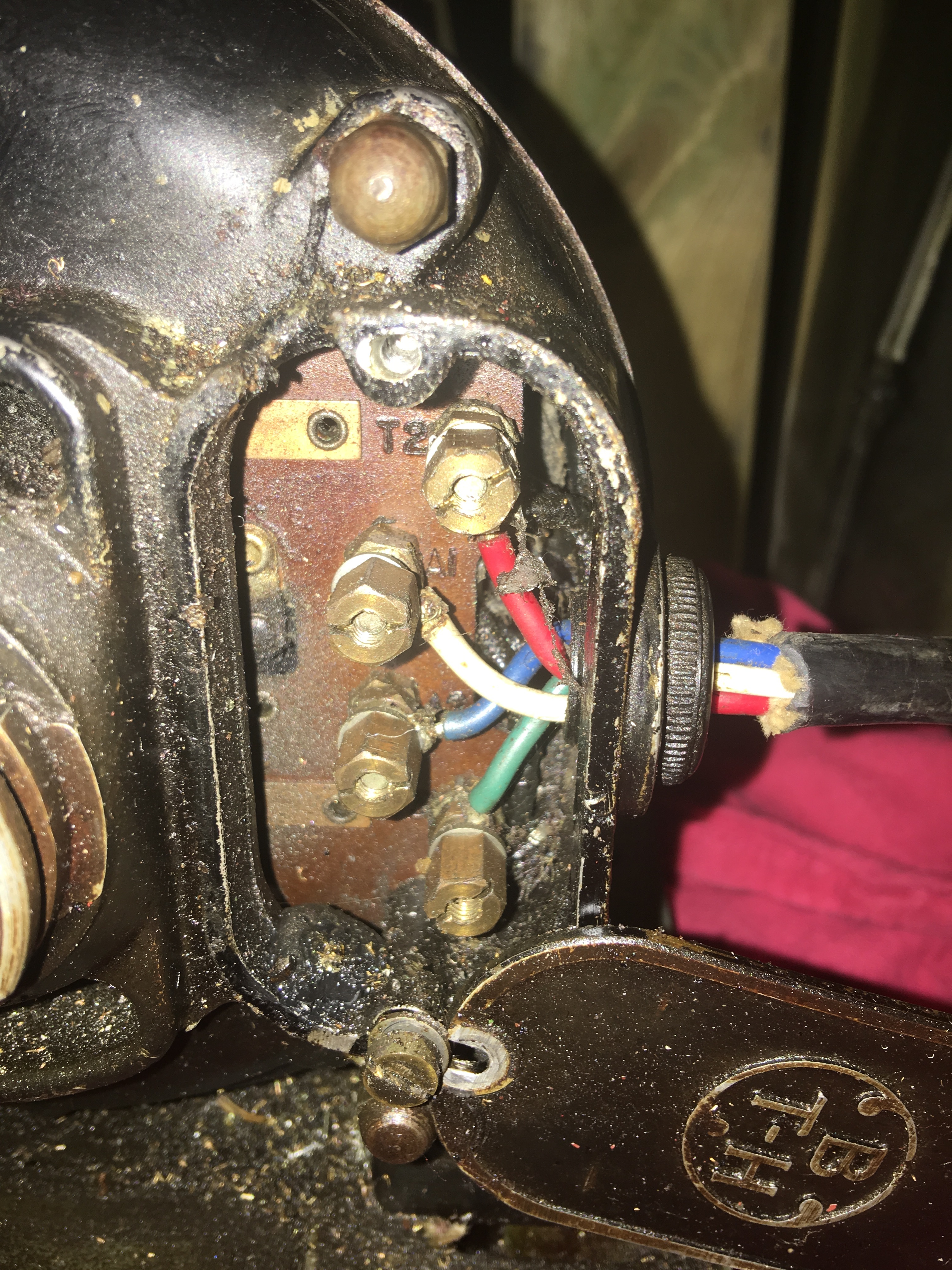
you have 2 separate windings for start and run , a live and neutral is supplied to opposite ends of each winding by the switch at the same time . as you change switch direction is swaps the live and neutral positions for the start winding .
the motor ‘t’ terminals are the start winding and the ‘A’ terminals are the run winding . the relative positions of live and neutral on the run terminals should not matter .
the start winding takes more amps for the high torque at start-up but the run winding then takes over and the current comes down .
you need to use a resistance meter to ensure the cables go through the switch correctly and best also to check for continuity across each winding and not to each other ( short circuit ) also check for infinite resistance from each winding to earth .
you need an earth connection and a decent mcb in the supply …prob 6 amp .
if you have trouble I should be able to come over on the weekend and think I also have some good 2.5 sy cable too :)