So I got bullied into considering fixing my bike again at BM last night, went home and pored over the wiring diagram.
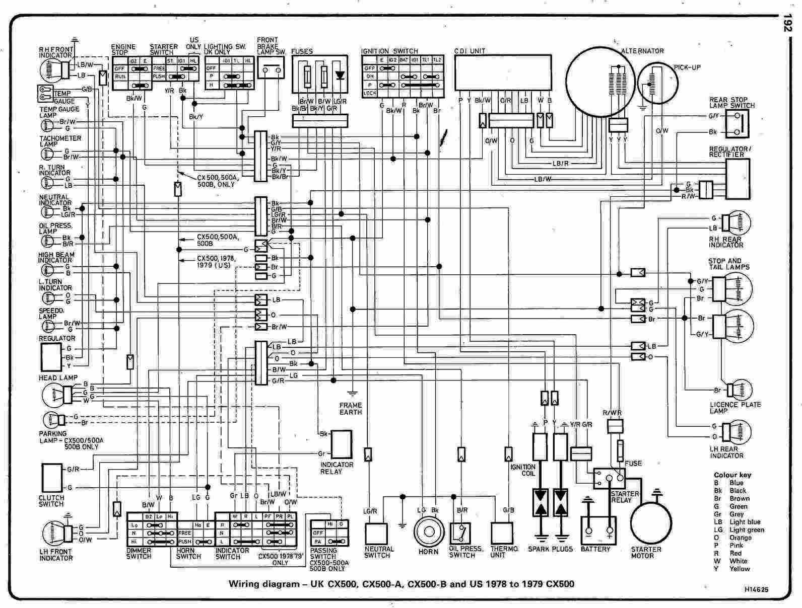
The charging circuit seems a bit weird, not least because there’s three wires on the DC side of the reg/rec. Googling around suggests this is an “activation wire” or to “tell the regulator what charging level is required” but I don’t understand why that’s necessary - is there a reason the reg/rec can’t just always be putting out 14.5V or whatever it can make from the coils? Smaller bikes and non-Hondas seem to often only have two wires on the DC side, are they missing out on some advantage?
The question that’s a bit closer to the problem I’m actually trying to solve is what voltages should I expect between those three lines on the DC side? Presumably the probably-positive to ground should be in the region of 12-14.5V?
I had one of these. Standard regs detect their own output at the reg itself, but that isn’t accurate due to the load at that particular point in the system. The remote wire is to be switched and connected ‘further down the line’ to ensure a more realistic reading. If that wire isn’t connected, the reg assumes 0v, and goes to work accordingly, feeding more and more current into the system until your lights explode. Probably.
So the rectifiers with only two lines on the DC side are just more prone to failure? I’m not looking to not connect one of the lines, I’m just trying to work out what is supposed to be going on as a pecursor to working out why it’s not doing that. I’m also a bit electrically retarded, so this could take some time…
So the theory is that the PD between the remote wire and ground tells the rectifier what the load on the system is and it can adjust its output voltage accordingly? Or between the remote wire and the positive? It certainly looks like things are using that remote wire as a ground, but I can’t find a circuit diagram that would behave like this.
This seems to be one of the more readable forms of a diagram of what might be inside:
where Vout is the red wire, Gnd’s bolted to the frame and C is that remote lead. So it’s a bit of a potential divider, whereby the PD between C and Gnd should always be low, and affects the resistance between them - as the PD rises so does the resistance, and the pd between Vout and ground increases?
Hrm, I guess if the idea is that Vout to C is a consistent 12V and that’s where things are connecting, the PD between C to ground will be the remainder of the rectifier’s output and can faff with all those transistors (and whatever the hell that diode with serifs is) to maintain that but still charge the battery with >12V…
This is turning me into a proper conspiracy theorist; is the functionality of a charging circuit kept a closely guarded secret in order to stop me being able to fix it at home and force me to take it to a shop?
No wonder everyone’s so concerned about electronic engines


